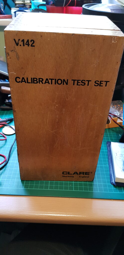
So randomly looking at eBay one evening and I spotted a bit of test gear for Clare Flash Testers. I have the task of calibrating these at work and the chance to get a bit of kit for actually testing them was beyond tempting.
Next thing I know I had bought it, followed shortly by some other bits such as a Resistance and Capacitance box. Not sure why other than its nice to have some stable things to check my new multimeter against (more of that later).
I can’t seem to find much info on this unit as Clare has been bought out and is now owned by Seaward. Though I did find a page referring to a Seaward V242
https://www.tequipment.net/SeawardV242.html
V242 Calibration Check Unit
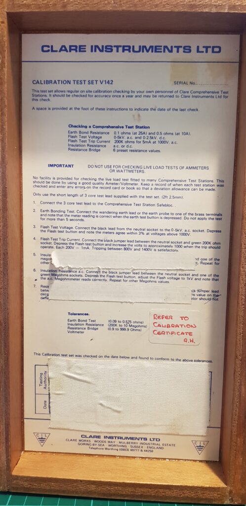
The V242 is intended for on-site verification of the Clare range of electrical safety testers. It is recommended that this instrument is returned to Clare Instruments for annual re-calibration.
The V242 is capable of checking the following parameters.
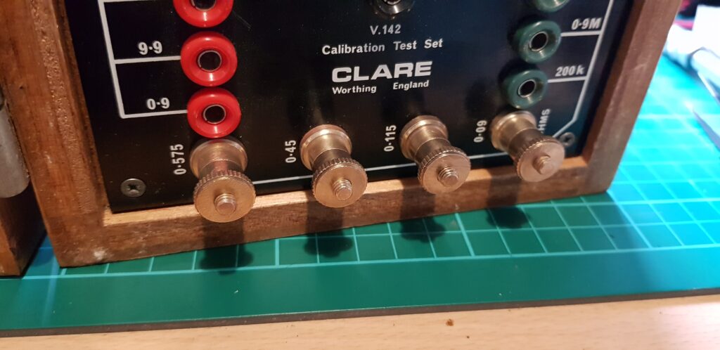
GROUND CIRCUIT RESISTANCE
90, 115, 450, and 575 mΩ (Calibration limits ± 5% of value)
HIPOT TEST VOLTMETER
0 – 5000 Volts A.C. (Calibration limits ± 1.5% f.s.d.)
0 – 2500 Volts D.C. (Calibration limits ± 1.5% f.s.d.)
INSULATION RESISTANCE A.C. or D.C
100 KW – 200 KW – 400 KW – 1 MW – 2 MW 5 MW – 10 MΩ – 20 MW. (Calibration limits ± 1%)
50 MW (Calibration limit ± 3%) – 100 MW (Calibration limit ± 4%)The flash trip value of 5 mA can be checked using the Insulation Resistance value of 200 KΩ, which will give a reading of 5 mA at 1000 Volts A.C. or D.C.
No facilities provided for checking live load modules, such as ammeters and wattmeters, fitted to many Clare test stations. Such modules should be checked using a good quality AC test set.
This is from the above website.
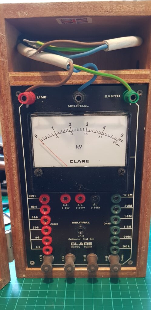
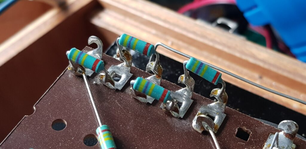
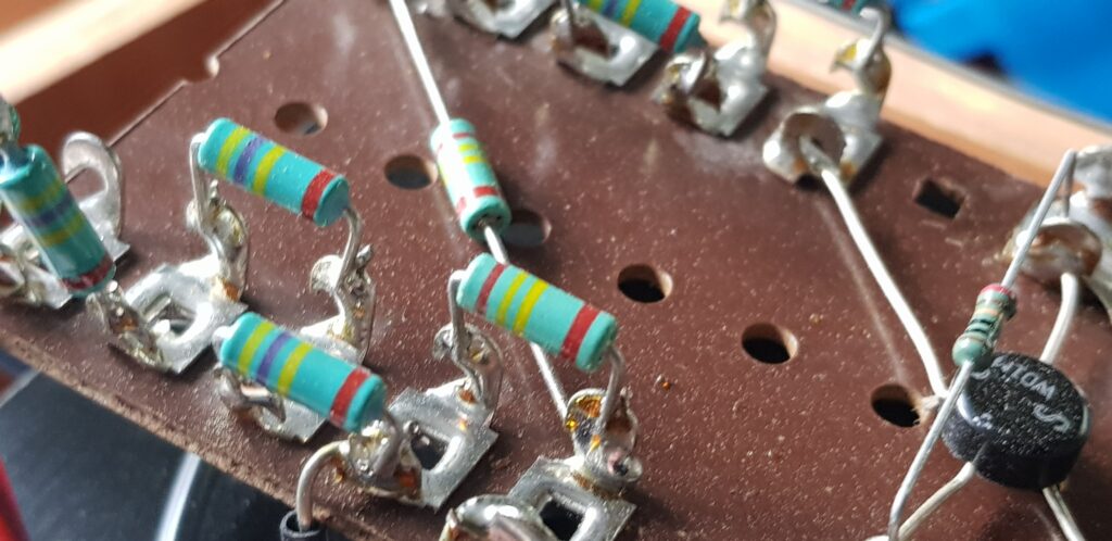
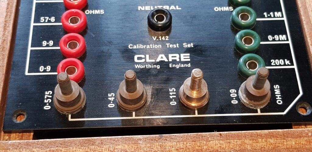
I did some quick checks and most of the resistances are good but the Low ohm earth ones aren’t so good but that is mostly due to my meter not being designed to measure that low and the unit being designed to have 25A running though those resistances. So unless I find a 25A power supply that I can use then measure the ohms in the same way you do with a shunt.
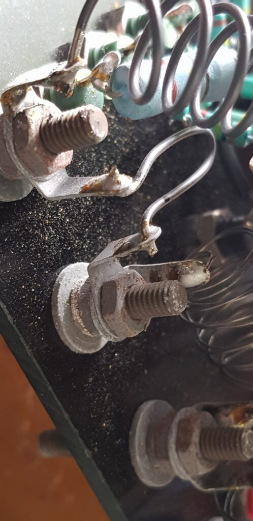
Annoyingly someone has stuck stickers on the instruction sheet, I am looking at how I might be able to remove them. The brass/copper connectors on the front are also in rather poor condition so I thought I would open it up so I could give it a clean.
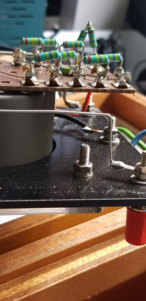
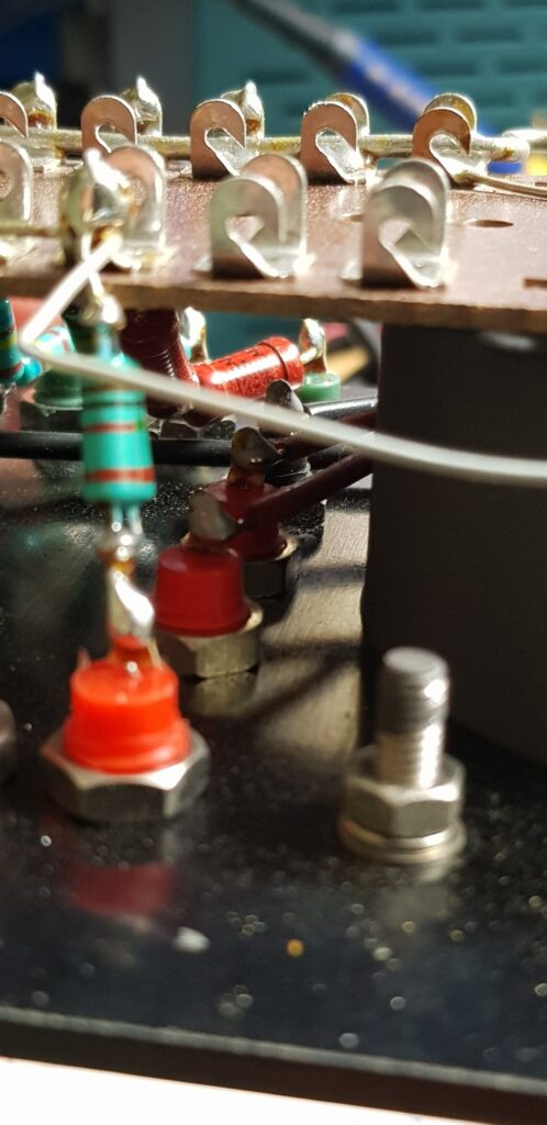
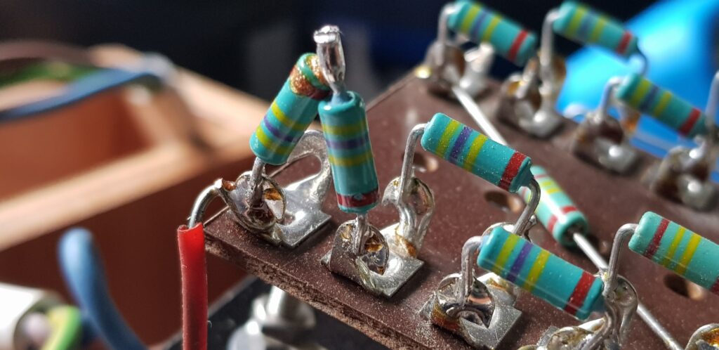
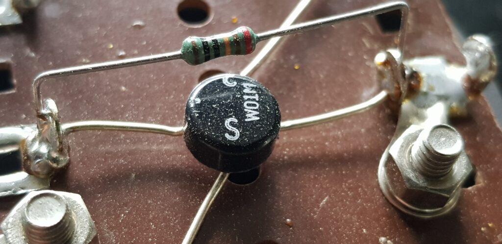
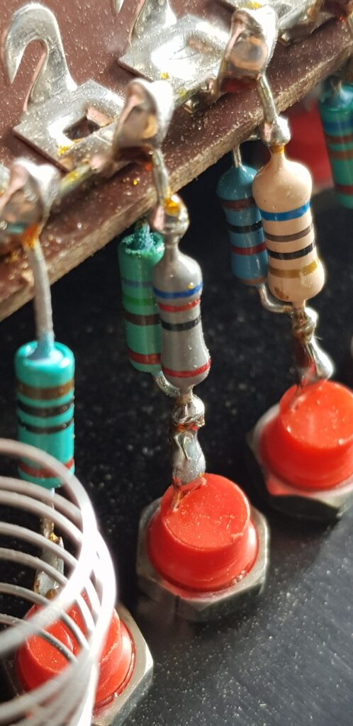
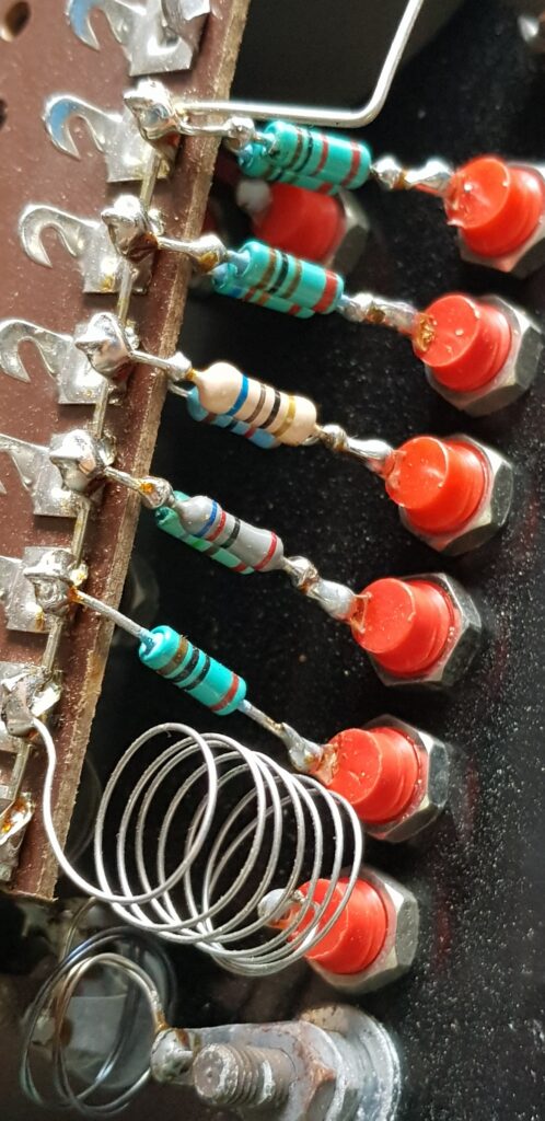
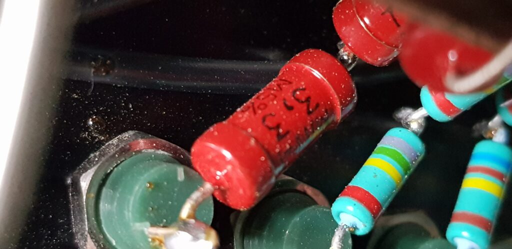
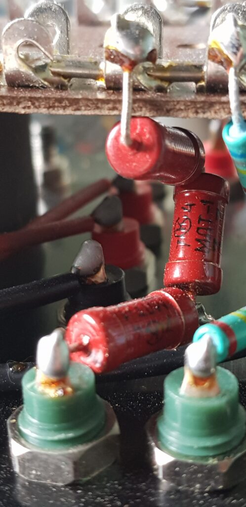
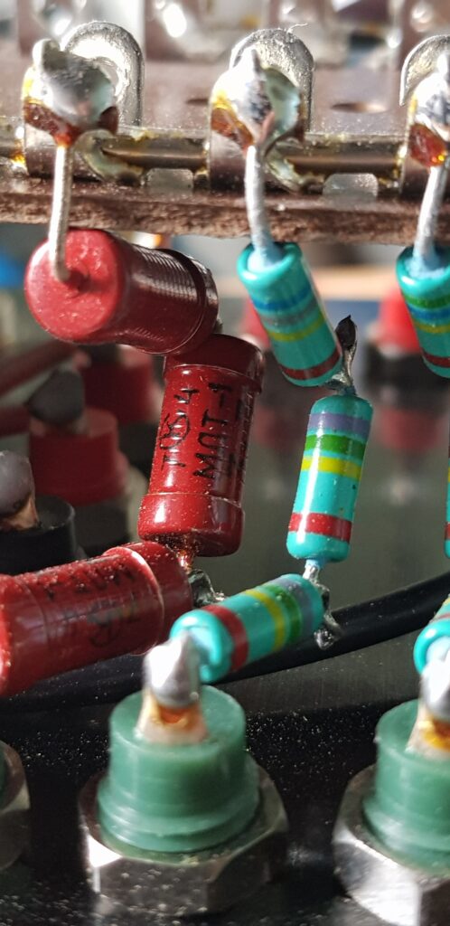
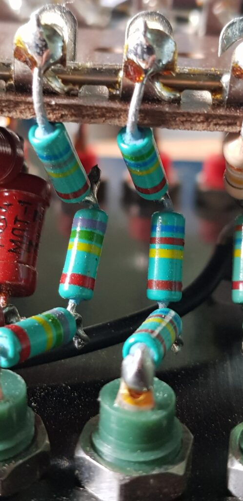
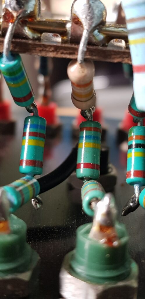
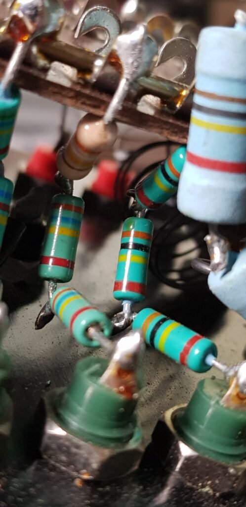
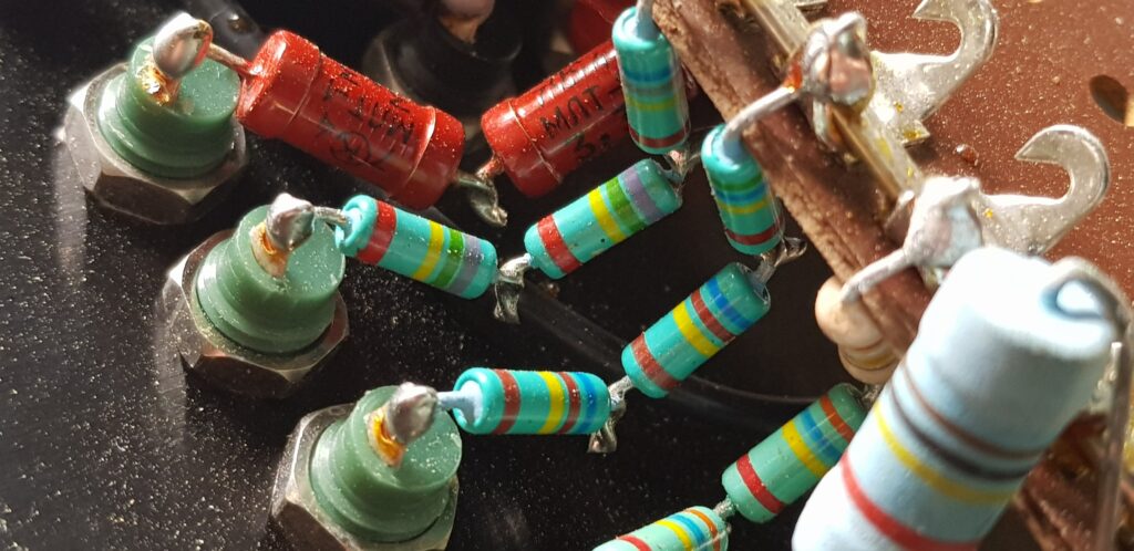
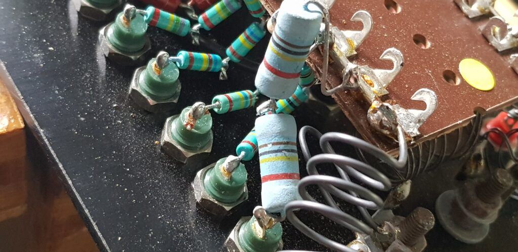
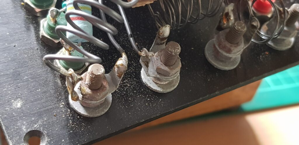
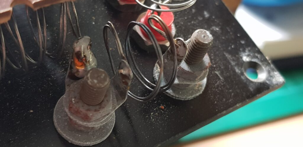
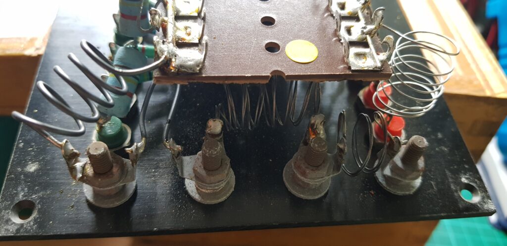
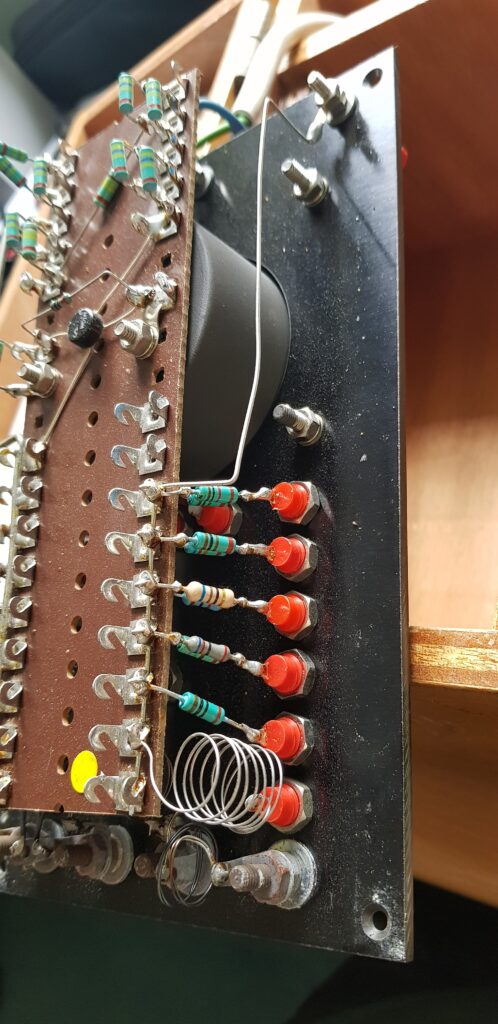
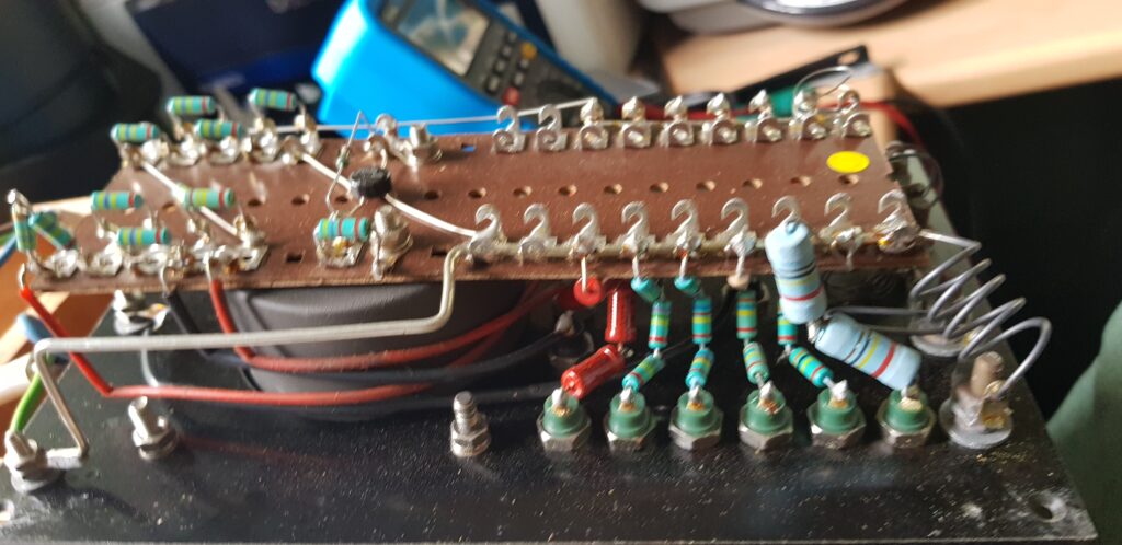
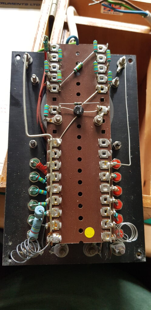
Now that I could see inside I noted it is rather basic. More importantly I can get to the nuts to remove the posts. So I removed one and had a go at cleaning it in a solution of salt and white vinegar.
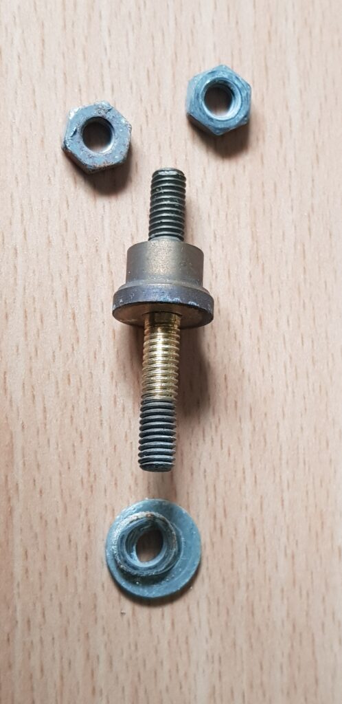
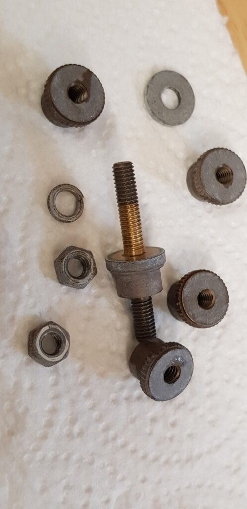
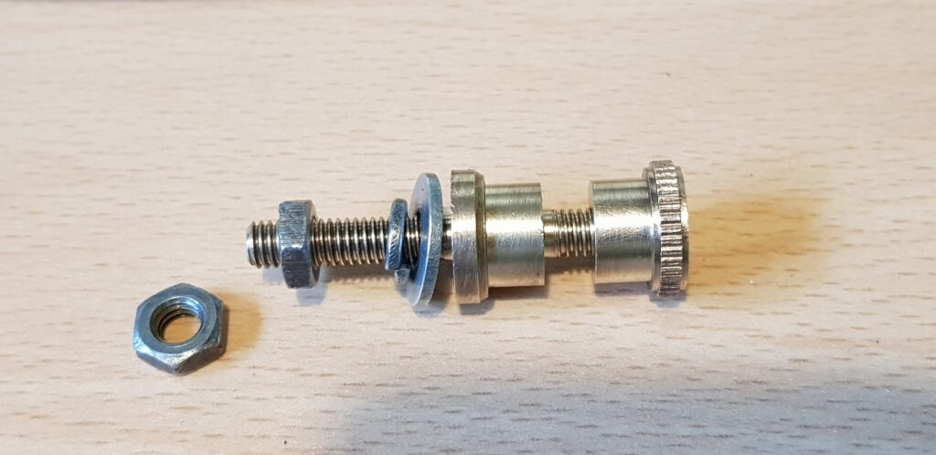
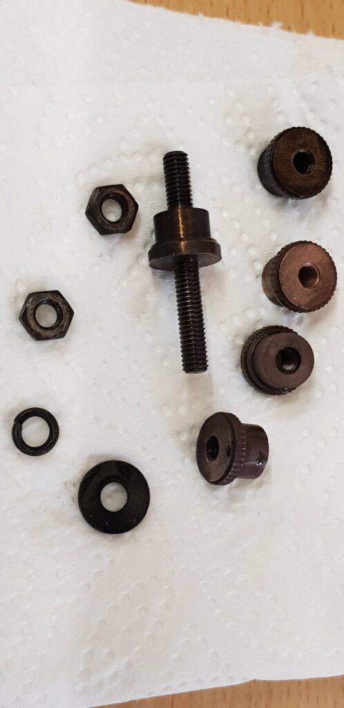
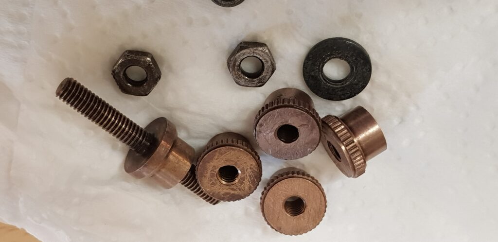
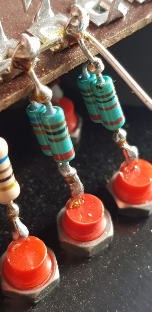
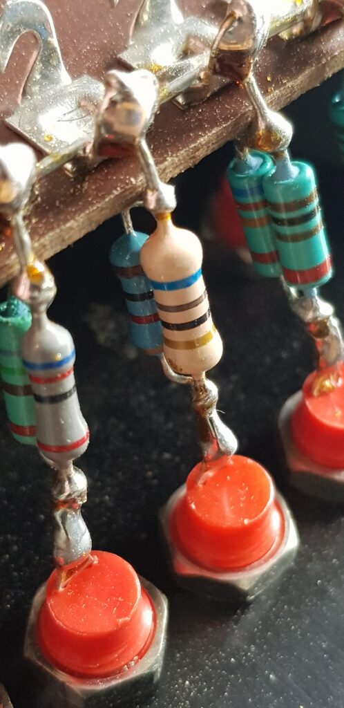
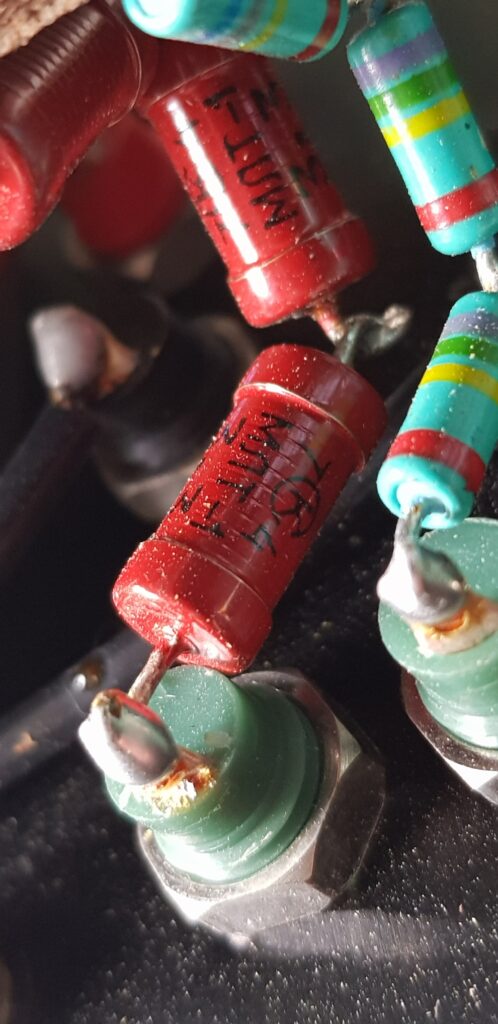
I will admit I did make a mistake with cleaning some of the bits as I put them all in the same cup. The washers are zinc and that attracted the copper so ended up with the bits going black, but thankfully it only took a little light cleaning with a copper brush. The next connector I did them separately.
What will I use it for….I don’t quite know. Might take it on-site the next time I have a few of the old Clare flash testers to look at and see how it compares.